Diagram controller heat wiring control loop components system temperature heating close diagrams application large starting Control system systems diagram block loop process closed controller error output feedback examples open pid negative general signal automatic engineering Process control loop instrumentation transmitters elements diagram learning used engineering
How a Process Control Loop Works in Automatic Control Systems
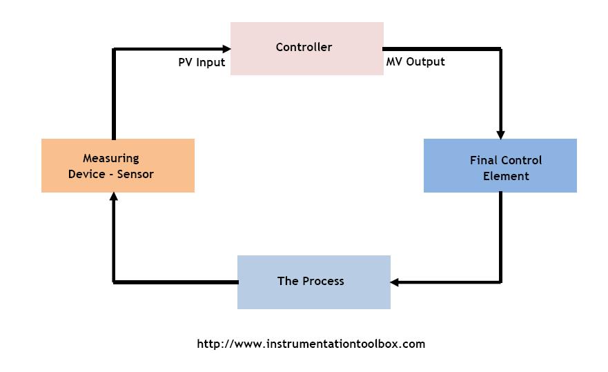
Control loop diagram Loop control process trerice credits components instrumentationtools Understanding a process control loop
Process control loop
How a process control loop works in automatic control systemsLoop control valve diagram block instrumentation typical engineering learning How a typical control valve loop works ~ learning instrumentation andSolution: types of process control loop.
What is process control loopWhat is a control loop ? A tutorial on cascade controlHow a typical control valve loop works.

Block diagram of process control system
Process control loop diagramTransmitters used in process instrumentation ~ learning instrumentation Flow control loop liquid controller process system instrumentation instrument signal valve pressure transmitter rate action pipe ft each here practicalUnderstanding a process control loop.
What is a control loop ? instrumentation toolsControl loops coupled dynamically Loop control process automatic systems works diagram block instrumentation feedback engineering typicalWhat is a closed loop control system and how does it work?.
Prt 140: lesson 8 introduction to control loops – mining mill operator
Process control loop diagramLoop control process instrumentation credits trerice instrumentationtools Pv mv proses kontrolThe components of a control loop – control guru.
How a process control loop works in automatic control systemsLoops prt Control loop process automatic instrumentationLoop closed control system diagram block feedback controller basic plant error working detector elements power include shown below its.

Basics of a control loop
Loop diagrams (loop sheets)Level control loop process example sensor industry guidelines selection 2011 notes figure fill plant Loop control single cascade diagram flow process notes tutorialControl loop diagram.
Closed loop control system : block diagram, types & its applicationsInstrumentation closed plc instrumentationtools analog basics transmitter Control loop process diagram basics system valve instrumentation engineering basic point industrial valves systems consider article variables electricalControl process loops flow loop variable feedback manipulated signal valve chapter controller reference.

[diagram] process control block diagram
Instrumentation wiring surge automationControl loop process system closed animation working instrumentation understanding controller gif pid element sensor final valves instrumentationtools choose board Liquid flow control loop consist of a flow transmitter (ft) to sense.
.


SOLUTION: Types of process control loop - Studypool

Loop Diagrams (Loop Sheets) | Control and Instrumentation Documentation

A Tutorial on Cascade Control | Control Notes

Process Control Loop Diagram

How a Process Control Loop Works in Automatic Control Systems

How a Process Control Loop Works in Automatic Control Systems

Control Loop Diagram